
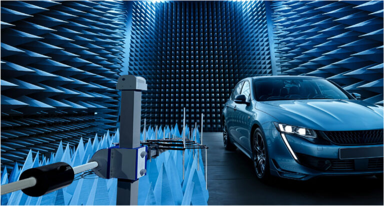
Automotive EMC: from component to complete vehicle
In the automotive sector, electromagnetic compatibility comes into play at every level, from electronic components and subassemblies up to the complete vehicle. ECUs, sensors, actuators, ADAS (Advanced Driver Assistance Systems), infotainment equipment, communication networks, radio systems, converters, electric motors, inverters and chargers must all operate simultaneously without generating excessive disturbances or being affected by their electromagnetic environment.
EMC testing therefore meets a dual requirement: controlling the conducted and radiated emissions of the vehicle and its equipment, and verifying their immunity to electrical disturbances and electromagnetic fields, sometimes at high levels and over wide frequency ranges.
The issues differ depending on the level considered (component, subassembly or complete vehicle) and also on the powertrain architecture. Hybrid and electric vehicles (EVs) in particular introduce new constraints linked to high electrical power, fast switching, converters, inverters, electric machines, high-voltage cables and charging systems.
Testing draws on various regulatory and technical standards such as UN Regulation No. 10, CISPR 12, CISPR 25, ISO 11451, ISO 11452, ISO 7637, ISO 10605, ISO 16750 and SAE standards, to which carmakers' own specifications are added.
HEMERA RF supports carmakers, suppliers and laboratories in defining and integrating EMC, RF and transient test facilities, from the bench used to qualify an ECU to installations for testing and monitoring a complete vehicle.
Regulations, standards and carmaker requirements: three levels to distinguish
In the automotive sector, an important distinction must be made between regulations, technical standards and carmaker specifications.
UN Regulation No. 10: the regulatory framework
UN Regulation No. 10, commonly known as UNECE R10, is a major regulatory reference for the EMC type approval of vehicles and of certain electrical or electronic subassemblies.
UNECE stands for United Nations Economic Commission for Europe.
In the countries, vehicles and equipment within its scope, this regulation sets out requirements relating in particular to electromagnetic emissions and immunity.
It therefore belongs to a regulatory type-approval framework.
CISPR, ISO and SAE: technical standards
CISPR, ISO and SAE standards define test methods, measurement conditions and, depending on the document, technical limits or levels.
They do not in themselves constitute a universal legal obligation.
Their applicability may result from:
- a type-approval regulation
- a carmaker specification
- a supplier specification
- a specific contract or programme.
This distinction is fundamental:
Regulations → what is required for type approval where applicable
Standards → how to characterise or test
Carmaker specifications → the manufacturer's particular requirements
Compliance with an ISO or CISPR standard does not, therefore, on its own mean that a vehicle is type-approved.
CISPR: controlling electromagnetic emissions
CISPR stands for Comité International Spécial des Perturbations Radioélectriques (International Special Committee on Radio Interference). It is part of the IEC (International Electrotechnical Commission).
In the automotive sector, two references are particularly important.
CISPR 25: equipment and subassemblies
CISPR 25 deals with radio disturbances, in particular in the context of protecting on-board receivers.
It is a major reference for characterising the conducted and radiated emissions of electrical or electronic components and subassemblies installed in the vehicle.
CISPR 12: complete vehicle
CISPR 12 covers radio disturbances generated by vehicles that may affect off-board receivers.
This distinction already identifies two test levels:
CISPR 25 → mainly equipment / subassembly
CISPR 12 → complete vehicle
ISO: immunity, transients and electrical environment
ISO stands for International Organization for Standardization.
Several series are particularly important in automotive EMC:
- ISO 11452: electromagnetic immunity of components and subassemblies
- ISO 11451: electromagnetic immunity of the complete vehicle
- ISO 7637: electrical transient disturbances, according to the applicable parts
- ISO 10605: ESD (electrostatic discharge)
- ISO 16750: environmental conditions and testing for on-board electrical and electronic equipment, including certain electrical loads.
The standards actually applicable, their editions, methods, levels and acceptance criteria must always be determined on the basis of the vehicle, the equipment, the target market and the requirements of the carmaker or programme.
SAE: the standards used in the US market
In the United States, automotive EMC testing may also draw on documents published by SAE International, an organisation historically known as the Society of Automotive Engineers.
SAE J1113: components and subassemblies
The SAE J1113 series brings together various EMC characterisation methods for automotive electrical and electronic equipment.
Depending on the applicable parts, it covers various conducted or radiated immunity and transient issues.
It notably includes the BCI (Bulk Current Injection) principle, widely used to characterise the RF immunity of components.
SAE J551: vehicle
The SAE J551 family covers various EMC methods applied at vehicle level.
Like ISO and CISPR standards, SAE documents should not be regarded as general regulatory obligations: their application depends on the carmaker, programme, contract and market concerned.
Japanese standards: JASO and carmaker requirements
The Japanese automotive market also has its own technical standards, which complement the international ISO and CISPR standards.
These include in particular the JASO (Japanese Automotive Standards Organization) standards, developed within the framework of JSAE (Society of Automotive Engineers of Japan). They cover various areas relating to vehicles and their electrical and electronic equipment, including certain electromagnetic compatibility issues.
As with the US SAE standards, Japanese standards must be distinguished from regulatory requirements: their applicability depends on the market, the carmaker, the type of equipment and the programme concerned.
Japanese carmakers may also impose their own specifications and validation methods. Groups such as Toyota, Honda, Nissan, Mazda, Subaru and Mitsubishi have internal requirements that may supplement or adapt the methods derived from international or Japanese standards.
For a supplier operating internationally, the same product may therefore have to be qualified against several standards and carmaker frameworks:
UN R10 → CISPR / ISO → SAE → JASO → carmaker-specific specifications.
This diversity must be taken into account from the design of the test setup, so as to cover the methods, frequency ranges, levels, modulations and functional criteria corresponding to the target markets and carmakers.
Carmaker requirements: beyond international standards
In practice, automotive equipment is generally not developed solely to meet an ISO or CISPR standard.
Carmakers define their own EMC specifications, which may adopt standardised methods while supplementing or adapting them.
These include, for example, specifications such as:
- Ford FMC1278
- BMW GS 95002
- Volkswagen TL 81000
as well as specifications specific to other carmakers and automotive groups such as Mercedes-Benz, Renault, Stellantis, Volvo, etc.
Depending on the carmaker and the programme, these specifications may require:
- wider frequency ranges
- higher immunity levels
- specific emission limits
- specific modulations
- precise cabling configurations
- particular conditions for high-voltage equipment
- specific functional criteria
- particular monitoring methods.
The exact reference, edition and level of the specification must always be checked for the programme concerned.
Two complementary levels: subassembly and complete vehicle
Automotive EMC must then be addressed at two distinct but complementary levels.
Components and subassemblies
Testing may cover:
- ECUs
- sensors
- actuators
- converters
- chargers
- ADAS equipment
- multimedia systems
- cameras
- radio and telematics equipment
- power electronic systems.
The aim is to characterise their emissions and verify their immunity before they are integrated into the vehicle.
CISPR 25, ISO 11452, ISO 7637, ISO 10605 and carmaker specifications play a particularly important role at this level.
Complete vehicle
Once the equipment has been integrated, the issue becomes a system-level one.
ECUs, wiring harnesses, converters, motors, communication systems, power electronics and RF equipment must be able to operate simultaneously without unacceptable electromagnetic interactions.
Vehicle testing may draw in particular on CISPR 12, ISO 11451 and UN Regulation No. 10, as well as on the carmaker's particular requirements.
A component that complies with its own specification does not therefore, on its own, guarantee the electromagnetic compatibility of the complete vehicle.
Emissions and immunity: the two sides of automotive EMC
It is important not to reduce automotive EMC to immunity testing alone.
Emissions: what the equipment or vehicle generates
Emission tests seek to determine whether a piece of equipment or a vehicle generates disturbances liable to affect other systems.
They may cover:
- conducted emissions
- radiated emissions
- disturbances generated on power supplies
- emissions from converters and inverters
- switching noise
- disturbances likely to affect radio bands.
Test setups may combine EMI receivers, analysers, LISNs, current probes, antennas and shielded or semi-anechoic chambers.
Immunity: what the equipment or vehicle must withstand
Immunity tests verify how the equipment behaves when exposed to a disturbed electromagnetic environment.
The phenomena may be:
- radiated
- conducted
- injected into wiring harnesses
- transient
- electrostatic.
The aim is not simply to check that the EUT remains powered: it must be determined whether its functions continue to meet the defined criteria during and after the test.
ISO 11452: immunity of components and subassemblies
The ISO 11452 series is a major reference for immunity testing of automotive components.
Different methods may be used depending on the phenomenon to be reproduced, notably exposure to a radiated electromagnetic field or injection of an RF disturbance onto the wiring harness.
The BCI (Bulk Current Injection) method, for example, injects a controlled RF current into a wiring harness to reproduce electromagnetic coupling.
A test chain may then consist of:
RF generator → power amplifier → injection device → measurement of applied current → EUT → functional monitoring.
For radiated methods:
RF generator → amplifier → antenna → electromagnetic field → EUT → functional monitoring.
This diversity often calls for several amplification, antenna and coupling technologies.
ISO 11451: complete-vehicle immunity
With ISO 11451, the EUT becomes the vehicle.
The scale of the problem therefore changes considerably.
A controlled electromagnetic environment must be generated around a complete vehicle while ensuring that it operates and is monitored.
Sizing the installation must take into account, in particular:
- vehicle dimensions
- test area volume
- exposure distance
- frequency ranges
- field levels
- required RF power
- antenna technologies
- field measurement and control
- vehicle position and orientation
- cabling and interfaces needed for the vehicle to operate
- installation safety.
The chamber, amplifiers, antennas, field probes and monitoring therefore form a single, coherent test system.
High fields and wide frequency coverage
Automotive testing may require high field levels, notably for certain carmaker specifications and certain sensitive functions.
Depending on the applicable methods and requirements, levels may reach several hundred V/m.
Tests must also cover a very wide frequency range, from low-frequency electrical phenomena and transients up to RF and frequencies of several GHz.
These values are not universal requirements: they depend on the standard, the method and above all the applicable carmaker specification.
To meet such requirements, a laboratory may need to combine:
- several generators
- several power amplifiers
- several families of antennas
- RF switching systems
- field probes
- power meters and power sensors
- injection devices.
Sizing the chain must take into account frequency, field level, available power, RF losses, antenna gain and test geometry.
Combustion, hybrid and electric vehicles: different environments
The powertrain architecture has a strong influence on the vehicle's electromagnetic environment.
Combustion-engine vehicles
In a combustion-engine vehicle, disturbances may originate in particular from:
- ignition systems
- alternators
- auxiliary electric motors
- ECUs
- actuators
- digital networks
- multimedia and RF systems.
These disturbances may be conducted through the electrical networks or radiated by the equipment and its wiring.
Hybrid and electric vehicles
Electrification introduces systems operating at much higher voltages, currents and power levels:
- traction battery
- traction inverter
- electric motor
- DC/DC converter
- OBC (On-Board Charger)
- charging systems
- compressors and electrical auxiliaries
- high-voltage cables.
Fast switching in power electronics generates voltage and current edges liable to produce disturbances over a wide frequency band.
These disturbances can propagate by conduction but also by radiation.
Electric vehicles: from high power to low-level radio signals
The electric vehicle (EV) is a particularly good illustration of the complexity of modern EMC.
A single vehicle may contain:
inverter and power electronics → high-speed digital networks → ECUs and sensors → radio systems operating on very weak signals.
A disturbance that is small compared with the electrical power of the traction drive can become significant if it falls within the band of a sensitive receiver.
Design and testing must therefore consider:
- sources of disturbances
- propagation paths
- high-voltage cables
- low-voltage cables
- shielding
- grounds
- filters
- interfaces
- receivers liable to be disturbed.
This issue is becoming increasingly important with electrification and the growing number of connected functions.
Electrical transients: reproducing the on-board power network environment
Automotive equipment must also withstand transient disturbances that may occur on the vehicle's electrical networks.
The ISO 7637 series defines various methods for reproducing some of these phenomena, depending on the applicable parts and the types of lines concerned.
Test setups may include transient generators, coupling networks, switching devices and measuring instruments.
The conditions to be reproduced depend heavily on the electrical architecture and the type of equipment.
Traditional low-voltage networks and electrified high-voltage architectures should therefore not be treated in the same way.
Radio and connectivity: a growing EMC challenge
The modern vehicle has also become a communications platform.
Depending on its equipment, it may include:
- broadcast radio
- GNSS (Global Navigation Satellite System)
- cellular telephony
- Bluetooth
- Wi-Fi
- keyless entry systems
- telematics
- vehicle-to-infrastructure communications, depending on the application.
The EMC challenge consists in particular in preventing an ECU, converter, display, digital network or power equipment from degrading radio reception.
This sometimes requires searching for very low-level disturbances in specific frequency bands.
EMC control then ties in directly with RF and radio issues.
Audio monitoring: detecting audible disturbances
During an immunity test, audio equipment may keep working without any outright failure while exhibiting:
- hissing
- clicking
- interference noise
- distortion
- level variations
- momentary dropouts.
A simple electrical check of the equipment will not necessarily detect these defects.
The test setup may therefore include audio monitoring to observe the signal during exposure and correlate an anomaly with the frequency and level of the applied disturbance.
Video monitoring: checking visual and ADAS functions
Modern vehicles feature numerous video functions: reversing cameras, surround view, displays, digital rear-view mirrors and ADAS.
An electromagnetic disturbance may cause:
- interference or artefacts
- lines in the image
- frozen images
- momentary loss of the video stream
- loss of synchronisation
- equipment restarts.
Video monitoring makes it possible to detect these phenomena during electromagnetic exposure.
For an ADAS function, it may also be necessary to monitor not only the video stream but the functional behaviour of the entire system.
Monitoring radio, networks and vehicle functions
Monitoring may also cover radio communications and in-vehicle networks.
The vehicle uses networks such as:
- CAN (Controller Area Network)
- LIN (Local Interconnect Network)
- Automotive Ethernet.
Depending on the application, the test system can monitor communications, ECU states, logged faults and functional parameters during exposure.
For radio systems, it may be necessary to monitor link presence, communication quality, loss of connection and the return to normal operation after the disturbance.
Controlling and monitoring the EUT during testing
An automotive immunity test is therefore not just about generating a disturbance.
The EUT (Equipment Under Test) must be placed in conditions representative of its real-world operation.
The architecture can be summarised as follows:
Disturbance generation → measurement of applied level → EUT control → audio / video / radio / network / function monitoring → anomaly detection → results acquisition.
Automation makes it possible to correlate an anomaly precisely with:
- the frequency
- the field level
- the injected RF current
- the type of modulation
- the applied transient
- the functional state of the vehicle or equipment.
It thus improves the repeatability, traceability and processing of tests.
From component bench to vehicle chamber
The diversity of applications leads to very different installations.
A component test bench may combine generators, amplifiers, antennas, BCI, LISNs, transient generators and monitoring systems.
For a complete vehicle, the dimensions and target levels may require a large semi-anechoic chamber, several amplification chains, various antennas, field probes, positioning systems and a much more extensive monitoring infrastructure.
In both cases, the aim remains the same: to reproduce the required electromagnetic environment accurately while simultaneously checking the functional behaviour of the EUT.
From standard to automotive test setup
Designing the setup begins with an analysis of:
- the regulatory framework
- the applicable standards
- the carmaker specification
- the tests to be covered
- the frequency ranges
- emission and immunity levels
- EUT dimensions
- the functions to be monitored.
HEMERA RF can then size and integrate:
- RF and microwave generators
- RF power amplifiers
- antennas
- EMI receivers and analysers
- LISNs
- current probes
- BCI systems
- field probes
- power meters and power sensors
- automotive transient generators
- ESD equipment
- shielded and semi-anechoic chambers
- positioning systems
- audio and video monitoring
- radio and network monitoring
- control and automation software.
The diversity of automotive standards frequently leads to combining several technologies and several specialised manufacturers.
The HEMERA RF approach to automotive projects
HEMERA RF acts as general contractor and multi-brand integrator for the design and delivery of automotive EMC test facilities, from component qualification benches to installations for complete vehicles.
Its involvement can cover the entire project: technical qualification of the requirement, analysis of regulatory and carmaker standards, sizing of emission and immunity chains, turnkey project management, sourcing from specialised manufacturers, hardware and software integration, automation, commissioning and metrology follow-up.
Independence from any single instrumentation manufacturer makes it possible to select the most suitable technologies for each function: EMI reception, RF generation, amplification, antennas, injection, transients, chamber, positioning, monitoring and automation.
This approach is particularly relevant when a laboratory must simultaneously cover several international standards, CISPR, ISO, SAE, JASO, and several carmaker specifications, with different levels, frequency bands and test methods.
Test facility availability: a requirement to consider from the design stage
HEMERA RF is also familiar with the operating constraints specific to automotive EMC laboratories. Downtime of a test facility can interrupt a qualification campaign, delay tests, take a chamber out of service and have a direct impact on programme timelines.
The reliability and maintainability of the installation are therefore among the criteria to be considered from the design stage.
The HEMERA RF approach favours the selection of specialised and reliable manufacturers, the availability of technical support, equipment maintainability and, where relevant, architectures that make diagnosis, maintenance and upgrading of the test facility easier.
The multi-brand approach offers a further benefit here: it makes it possible to look beyond the nominal performance of a piece of equipment and also take into account its reliability, support, longevity and fit with the laboratory's operating constraints.
Calibration management, maintenance and anticipation of downtime can also be built into this approach to help keep the test facility available over the long term.
Experience with major automotive players
HEMERA RF draws on experience gained through projects carried out for carmakers, suppliers and test laboratories in the automotive sector.
These projects cover combustion, hybrid and electric architectures as well as emission, immunity, transient, high-field, radio and functional monitoring issues.
This experience, combined with a multi-brand approach and the ability to manage turnkey projects, enables HEMERA RF to design high-performance, automated and scalable test facilities suited both to international standards and to the particular requirements of carmakers.
Frequently asked questions
Frequently asked questions
Automotive
Which EMC standards apply to the automotive industry?
Automotive testing may involve:
• CISPR 25 for radio disturbances
• ISO 11451 / ISO 11452 for electromagnetic immunity
• ISO 7637-2 for certain conducted electrical transients
• specific requirements defined by vehicle manufacturers
The test bench must be sized for the methods, frequencies and levels actually required.
How do I choose a transient generator for automotive testing?
The factors to consider are:
• standards to be covered
• vehicle manufacturer specifications
• waveforms
• amplitudes
• output impedances
• electrical characteristics of the equipment under test